 Skip to content

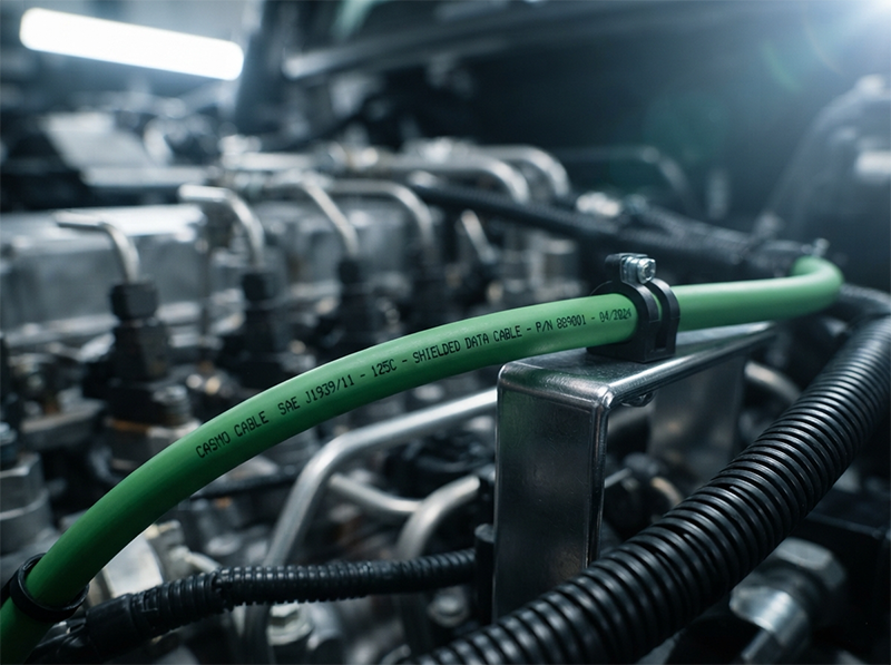
A major fleet operator watches profits evaporate. Their new truck model is throwing intermittent, or ‘ghost,’ Diagnostic Trouble Codes (DTCs), triggering a cascade of costly warranty claims, wasted technician hours, and crippling vehicle downtime. The culprit? An elusive data corruption issue on the CAN bus network. The original cable supplier insisted their product was compliant with SAE J1939/11, and on paper, it was. The impedance was correct, and the pairs were twisted. Yet, the network was fundamentally unreliable in the real world.
This scenario is far from unique. It highlights a critical gap between paper compliance and operational reliability, a gap that our engineers frequently encounter in the field.
"A 'compliant' J1939-11 cable from a previous supplier used a cheap 85% coverage aluminum foil shield. In the noisy environment of a modern diesel engine bay, EMI was bleeding through, causing intermittent data corruption. We replaced a section with a CASMO cable featuring a 95% coverage tinned copper braid over foil. The DTCs vanished. The lesson: J1939-11 compliance is the starting line, not the finish line. Shielding effectiveness in a real-world, 2000-hour-a-year duty cycle is a metric you won't find on a basic spec sheet."
— Vehicle Network Specialist, troubleshooting intermittent CAN bus faults
The challenge of selecting the right SAE J1939/11 cable is not about finding a supplier who can read a standard; it's about partnering with one who understands the punishing physics of a heavy-duty environment. This article moves beyond the basic definitions to provide an engineering-level guide on how to specify a J1939 cable that ensures network integrity from the production line to a million miles on the road.
The Short Answer: Key Selection Criteria
SAE J1939/11 defines the physical layer for 250 kbit/s CAN networks in heavy-duty vehicles. It specifies a shielded, 120-ohm twisted-pair cable to ensure reliable data transmission. However, the standard allows for wide variation in how these requirements are met. True reliability depends not just on meeting these baseline specs, but on the quality of the materials and construction—specifically, the shielding effectiveness and the jacket's resilience to environmental stress.
Why This Specification Matters
For an R&D engineer designing a new vehicle platform or a procurement manager sourcing components for a critical system, overlooking the nuances of the J1939 cable specification can have severe financial and reputational consequences. The J1939 network is the central nervous system of any modern heavy-duty vehicle, carrying critical messages between the engine, transmission, brakes, and diagnostic systems. A single corrupted data packet can lead to anything from a false warning light to reduced engine performance or, in the worst case, a complete network shutdown.
Across hundreds of projects compliant with IATF 16949 for automotive and ISO 13485 for medical devices, we at CASMO CABLE have seen firsthand how an under-specified cable becomes the weakest link. The belief that "any compliant cable will do" leads to costly redesigns, emergency field retrofits, and damage to brand credibility. This guide will dissect the three pillars of a truly robust J1939/11 cable: impedance control, shielding effectiveness, and environmental resilience. Understanding these will empower you to ask the right questions and move beyond the datasheet.
Core Technical Deep-Dive: Deconstructing a High-Performance J1939 Cable
The SAE J1939/11 standard provides the blueprint. But excellence is found in the execution and the material science behind each component. Let's break down what truly matters.
The Twisted Pair & Impedance Control: A Game of Microns
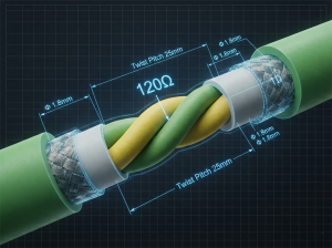
The standard calls for a twisted-pair cable with a characteristic impedance of 120 ohms (±12 ohms). This is fundamental. The twisting cancels out electromagnetic interference from external sources and minimizes crosstalk between the CAN_H and CAN_L signal lines. Maintaining a consistent 120-ohm impedance along the entire length of the cable is crucial to prevent signal reflections, which corrupt data packets.
But what ensures this consistency? It's a matter of manufacturing precision.
- Conductor Quality: Using high-purity, concentric copper conductors is the first step.
- Insulation Uniformity: The thickness and dielectric constant of the insulation material must be perfectly uniform. Any variation changes the distance between conductors, which directly alters impedance.
- Dimensional Tolerance: This is a hidden factor with huge cost implications. For a Tier 1 automotive supplier we work with, their automated harness assembly line (using Komax machines) requires a cable with extremely tight outer diameter (OD) tolerance. A cheaper cable with an OD variance of ±0.4mm caused a 10% scrap rate during automated stripping and crimping. Our cable, held to a ±0.1mm tolerance, runs flawlessly. The initial cost saving was completely negated by rework and production delays.
The Shield: Your First and Last Defense Against EMI
This brings us back to our opening story. The single most important factor for network reliability in an engine bay is shielding. The J1939 standard simply says "shielded." This is where a spec sheet can be dangerously misleading.
- Material: Aluminum foil is cheap but less effective against low-frequency magnetic fields (common from alternators and starters) and can crack under vibration. Tinned copper offers superior conductivity and is far more durable.
- Coverage: 85% coverage might sound good, but that 15% gap is a massive doorway for high-frequency noise from injectors and ignition systems. A 95% or higher coverage is the professional standard for mission-critical applications.
- Construction: The gold standard is a combination of an aluminum/polyester foil tape (for 100% high-frequency coverage) overwrapped with a tinned copper braid (for low-frequency performance and mechanical strength). This braid-over-foil construction provides the robust J1939 shielding requirements needed for the harshest electrical environments.
For a detailed analysis of your application's EMI risks, consult our engineering team.
The Jacket: Resisting a World of Abuse
A design engineer for a leading agricultural equipment OEM shared a case with us. They specified a J1939-11 cable with a standard -40°C to 105°C PVC jacket for a combine harvester. After one harvest season in a cold climate, network failures began. The issue wasn't the static temperature rating. The PVC jacket became brittle below freezing, and the punishing 3 Grms machine vibration caused micro-cracks. Hydraulic fluid and moisture seeped in, corroding the shield and causing the network to fail.
The "harsh environment" defined by SAE is a baseline. A real-world application adds vibration, abrasion, and chemical exposure simultaneously. The jacket material is your only protection.
| Jacket Material | Temp. Range | Low-Temp Flexibility | Chemical/Oil Resistance | Abrasion Resistance |
|---|---|---|---|---|
| PVC | -40°C to 105°C | Poor (becomes brittle) | Fair | Good |
| TPE | -50°C to 125°C | Good | Good to Excellent | Very Good |
| PUR (Polyurethane) | -55°C to 105°C | Excellent (maintains flex) | Excellent | Excellent |
The fix for the harvester was a PUR-jacketed cable. It cost more upfront but eliminated field failures, saving thousands in warranty and downtime. This demonstrates that the choice of jacket material is a critical engineering decision, not an afterthought.
The Engineer's Decision Framework
When specifying your next J1939 cable, use this framework to move beyond the price-per-meter:
- If your primary challenge is electrical noise (e.g., crowded engine bays, high-current components), then demand specifics on shielding. Ask for braid-over-foil construction with >95% tinned copper braid coverage. Do not accept "foil shield" as an answer.
- If your application involves vibration, flexing, or extreme temperatures (e.g., off-highway equipment, articulated chassis), then prioritize the jacket material. A PUR or high-grade TPE jacket is a non-negotiable investment over standard PVC.
- If you are running high-volume automated production, then mechanical tolerance is your most critical metric. Demand a specification for outer diameter (OD) and concentricity, and request samples to test on your own equipment. A tolerance of ±0.1mm should be your target.
Beyond the Datasheet: Key Questions for Your Supplier
Sourcing specialty cables at scale requires a partnership, not just a purchase. Before you finalize your spec sheet, ask your potential supplier these questions:
- Can you provide shielding effectiveness data (in dB) for this cable, not just the coverage percentage?
- What is your process control for maintaining impedance consistency batch-to-batch?
- Can you provide data on this jacket material's performance after aging and exposure to common industrial fluids (e.g., diesel, hydraulic oil)?
Talking to an engineer directly can uncover risks and opportunities a datasheet will never reveal.
Final Thought
We began with the story of a fleet haunted by ghost DTCs. That story wasn't about a faulty component; it was about a misplaced assumption—the assumption that "compliant" means "reliable." The fix wasn't just a better cable; it was a better understanding of the physics involved. In the world of heavy-duty vehicle networks, the right cable isn't a commodity you source; it's a critical component you engineer. In extreme environments, the right cable isn't an accessory; it's the bedrock of reliability.
Frequently Asked Questions
1. What is the main difference between SAE J1939/11 and J1939/15?
SAE J1939/11 specifies the requirements for the main network backbone cable, which is a shielded twisted pair with a 120-ohm impedance. SAE J1939/15, in contrast, defines the requirements for unshielded twisted pair cable, which is typically used for shorter, less critical "stub" connections to individual ECUs in a more controlled electrical environment. Using a J1939/15 cable on the main backbone is a common cause of network instability.
2. Why is 120-ohm characteristic impedance so critical for a J1939 network?
The CAN bus standard, on which J1939 is based, requires termination resistors of 120 ohms at each end of the main bus. For maximum signal power transfer and to prevent destructive signal reflections, the impedance of the cable itself must match the termination resistors. Any significant deviation from 120 ohms along the cable's length will cause signal degradation, increasing the bit error rate and compromising data integrity.
3. Is a simple aluminum foil shield enough for most J1939 applications?
For static, low-noise environments, a foil shield might be adequate. However, for any heavy-duty vehicle application—especially near the engine, alternator, or high-power inverters—a foil-only shield is insufficient. It lacks the low-frequency magnetic field shielding and the mechanical durability to withstand vibration. A combination of foil and a high-coverage (>95%) tinned copper braid is the professionally recommended solution for robust EMI protection.
4. What jacket material is best for a J1939 cable in cold weather with high vibration?
Polyurethane (PUR) is the superior choice. Unlike PVC, which becomes rigid and brittle at low temperatures, PUR maintains its flexibility well below freezing (-55°C or lower). This prevents the jacket from cracking under vibration, which would expose the shield to moisture and corrosive fluids. High-grade Thermoplastic Elastomers (TPE) are also a good alternative, offering a balance of flexibility and chemical resistance.
5. How does J1939 cable outer diameter (OD) tolerance affect my production costs?
In automated harness manufacturing, machines are calibrated for a specific cable OD for cutting, stripping, and crimping. If the OD varies significantly, the stripping blades may cut into the conductor (creating a weak point) or fail to remove the insulation cleanly. This leads to failed connections, increased material scrap, machine downtime for recalibration, and higher labor costs for manual rework, often erasing any initial savings from a cheaper cable.
6. What are the consequences of using a cheap, non-compliant J1939 cable?
The consequences range from frustrating to catastrophic. Initially, you may see intermittent "ghost" fault codes, reduced fuel efficiency, or unstable communication. Over time, as the cable degrades due to vibration, heat, or fluid exposure, these issues can become permanent, leading to vehicle downtime, expensive diagnostic and repair bills, failed emissions tests, and significant damage to your brand's reputation for reliability.
References & Standards
- SAE J1939-11: Physical Layer, 250K bits/s, Twisted Shielded Pair
- SAE J1939: Recommended Practice for a Serial Control and Communications Vehicle Network
- ISO 11898-2: Road vehicles — Controller area network (CAN) — Part 2: High-speed medium access unit
- CASMO CABLE: Technical Datasheet - J1939 Heavy-Duty CAN Bus Cable
