
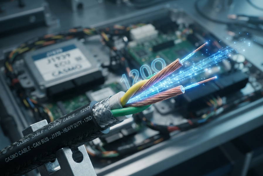
A 40-meter off-highway vehicle backbone is plagued by intermittent CAN errors. ECUs drop off the network randomly under high load, bringing operations to a halt. The design team verifies the network: the 120Ω terminators at both ends are precision metal-film components, verified flawlessly with a multimeter. The logic seems unassailable: 120Ω resistors mean a 120Ω network. Yet, signal integrity analysis reveals severe signal reflections. The culprit isn't the terminators; it's the unshielded J1939/15 cable whose characteristic impedance had drifted to 105Ω due to crushed dielectric geometry.
This scenario exposes a critical, often overlooked blind spot in CAN bus design: the fundamental difference between a terminating resistor and J1939 cable impedance.
"We were troubleshooting intermittent CAN errors on a 40-meter off-highway vehicle backbone. The 120Ω terminators at both ends were precision metal-film components, verified with a multimeter. The logic was simple: 120Ω resistors mean a 120Ω network. But signal integrity analysis showed severe reflections. The culprit wasn't the terminators; it was a tight-lay, unshielded J1939/15 cable whose characteristic impedance had drifted to 105Ω due to crushed dielectric geometry. A perfect 120Ω resistor on a 105Ω cable creates a ~14% impedance mismatch, acting as a reflection point. We switched to a J1939 cable with a controlled twist pitch and consistent dielectric thickness, guaranteeing a true 120Ω ± 10% characteristic impedance. The reflections vanished. The resistor doesn't set the network impedance; the cable geometry does."
— Design engineer, integrating a 40m CAN backbone for an off-highway vehicle
The challenge of specifying the right cable for a heavy-duty CAN bus is not simply about sourcing a shielded twisted pair; it's about partnering with a manufacturer who understands the physics of transmission lines. This article moves beyond the basic terminal resistor discussion to provide an engineering-level guide on why 120Ω is a geometric property of the cable itself, and how failing to control it compromises the entire network.
The Short Answer: Key Selection Criteria
In SAE J1939 and CAN bus networks, 120Ω is not just the value of the terminating resistors; it is the required characteristic impedance of the cable itself. While terminators absorb signals at the ends of the bus, the cable's physical geometry (conductor diameter, insulation thickness, and twist pitch) dictates how the signal travels. If the cable's characteristic impedance deviates significantly from 120Ω, signal reflections occur, corrupting data and causing intermittent network failures, regardless of how perfect the terminating resistors are.
Why This Specification Matters
For an R&D engineer designing a new vehicle platform or a procurement manager sourcing components for a critical system, overlooking the nuances of J1939 cable impedance can have severe financial and operational consequences. The J1939 network is the central nervous system of any modern heavy-duty vehicle, carrying critical messages between the engine, transmission, brakes, and diagnostic systems. A single corrupted data packet due to signal reflection can lead to anything from a false warning light to a complete network shutdown.
Across hundreds of projects compliant with IATF 16949 for automotive and ISO 13485 for medical devices, we at CASMO CABLE have seen firsthand how an under-specified cable becomes the weakest link. The belief that "any J1939 labeled cable will do as long as the resistors are right" leads to costly field diagnostics, emergency redesigns, and warranty claims. This guide will dissect the transmission line theory behind 120Ω, the dangers of over-engineering, and the manufacturing precision required to maintain impedance consistency. Understanding these principles will empower you to specify cables that ensure flawless data transmission from the production line to the field.
Core Technical Deep-Dive: Deconstructing 120Ω Characteristic Impedance
The SAE J1939/11 standard mandates a 120-ohm twisted-pair cable. However, the standard assumes the manufacturer maintains strict geometric control. Excellence in a CAN bus physical layer is found in the execution of the cable's physics.
The Physics of 120Ω: It's Geometry, Not Just a Resistor
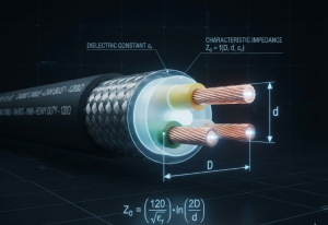
Characteristic impedance ($Z_0$) is not a resistance you can measure with a standard multimeter. It is the ratio of voltage to current for a wave traveling down the cable. For a twisted-pair cable, $Z_0$ is determined by the physical geometry of the pair and the dielectric constant of the insulation material.
The simplified formula for a twisted pair is roughly:
$Z_0 \approx \frac{138}{\sqrt{\varepsilonr}} \times \log{10}\left(\frac{D}{d}\right)$
Where:
- $D$ = Distance between the centers of the two conductors.
- $d$ = Diameter of the conductor.
- $\varepsilon_r$ = Dielectric constant of the insulation.
If a manufacturer alters the wall thickness of the insulation (changing $D$) or uses a cheaper, thinner conductor (changing $d$), the characteristic impedance shifts[^1]. When this shifted impedance meets the fixed 120Ω terminating resistor at the end of the bus, an impedance mismatch occurs. This mismatch acts as a partial reflector, bouncing signal energy back down the line[^2]. The result is signal ringing (oscillation) and distorted data edges, leading to bit errors and frame loss.
The Over-Shielding Trap: When 'More' Becomes 'Less'
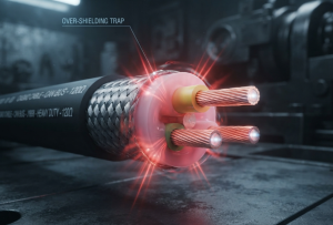
In harsh environments, engineers often specify heavy double-shielded cables, assuming that more shielding equates to better signal integrity. However, this good intention can backfire if the manufacturer doesn't account for the geometric impact of the shielding.
"For a heavy-duty agricultural platform, we specified a heavy double-shielded J1939/11 cable, assuming more shielding meant better signal integrity for a 250 kbps network. But the extra shielding and thick jacket compressed the inner dielectric, shifting the cable's characteristic impedance from 120Ω to 145Ω. Even with perfect 120Ω terminators, the 25Ω mismatch caused ringing and dropped frames at high ECU load. We switched to a single-shielded, precision-twisted J1939/11 cable that maintained a strict 120Ω ± 5% characteristic impedance. The network became flawless. Over-engineering the shield compromised the geometry that actually defined the impedance."
— Systems integrator, designing a CAN network for severe-EMC agricultural equipment
This case highlights a critical engineering principle: physical rules do not care about intent. If adding a heavy shield compresses the inner dielectric layer (reducing $D$), the characteristic impedance drops. If the manufacturer adds layers outside the dielectric without adjusting the inner geometry, the impedance can rise. The solution is not to abandon shielding, but to specify a cable where the shielding is applied without compromising the precise 120Ω geometry of the twisted pair.
How Impedance Mismatch is Manufactured (And How We Prevent It)
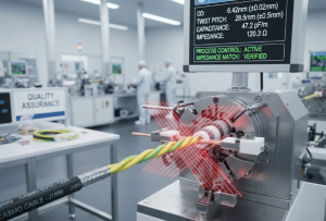
Maintaining 120Ω ± 10% (or ideally ± 5%) is a matter of high-precision manufacturing. At CASMO CABLE, we control this through rigid process parameters:
- Concentric Conductor Extrusion: Using high-purity copper with a perfectly consistent diameter ($d$).
- Foamed Dielectric Control: Using precisely extruded PE or foamed PP to maintain a consistent distance ($D$) between conductors, while keeping the dielectric constant ($\varepsilon_r$) stable.
- Twist Pitch Synchronization: The twist pitch (lay length) must be uniform. Variations in the twist pitch locally alter the impedance, creating multiple reflection points along the cable.
To illustrate why sourcing matters, consider the tolerances we enforce compared to standard market offerings.
| Geometric Parameter | Typical Market Tolerance | CASMO Control Tolerance | Impact on Characteristic Impedance ($Z_0$) |
|---|---|---|---|
| Conductor Diameter ($d$) | ± 0.03 mm | ± 0.005 mm | Smaller $d$ increases $Z_0$; larger $d$ decreases $Z_0$. |
| Insulation Wall Thickness | ± 0.05 mm | ± 0.01 mm | Thinner wall decreases $D$, lowering $Z_0$; thicker wall raises $Z_0$. |
| Twist Pitch (Lay Length) | ± 10% | ± 3% | Inconsistent pitch causes localized $Z_0$ drift and reflections. |
| Resulting Impedance ($Z_0$) | 105Ω to 145Ω | 114Ω to 126Ω | 120Ω ± 10% guaranteed, minimizing signal reflections. |
For high-speed CAN networks spanning long distances, this level of manufacturing precision is the difference between a stable backbone and a diagnostic nightmare. For detailed impedance profiles, consult our engineering team.
The Engineer's Decision Framework
When specifying your next J1939 cable, use this framework to move beyond the terminal resistor and focus on the cable's physical layer:
- If you are designing a long backbone (>10 meters), do not assume standard J1939/15 cables will suffice. You must specify a cable with a guaranteed 120Ω ± 5% characteristic impedance. Request a Time Domain Reflectometer (TDR) plot from the manufacturer to verify impedance consistency along the entire length.
- If you are operating in a severe-EMI environment, prioritize a braid-over-foil shield, but verify with the manufacturer that the shielding application process does not compress the internal dielectric or alter the twist pitch.
- If you are evaluating tier-1 suppliers based on cost, look past the unit price. A supplier that cannot provide TDR data or geometric tolerances is likely selling a cable with drifting impedance. The cost of a 20% cheaper cable will be paid in EMC test failures and field diagnostics.
Beyond the Datasheet: Key Questions for Your Supplier
Sourcing specialty cables at scale requires a partnership, not just a purchase. Before you finalize your spec sheet, ask your potential supplier these critical questions:
- What is the guaranteed characteristic impedance tolerance of this cable, and can you provide TDR data to prove it?
- How do your manufacturing processes ensure the twist pitch and dielectric thickness remain consistent across a 500-meter drum?
- If I specify an additional shield or a special jacket, how will you adjust the inner geometry to maintain the 120Ω characteristic impedance?
Talking to an engineer directly can uncover risks and opportunities a datasheet will never reveal.
Final Thought
We began with the story of a 40-meter CAN backbone failing despite having perfect 120Ω resistors. That failure wasn't a faulty component; it was a fundamental misunderstanding of transmission line physics. The fix wasn't a better resistor; it was a better cable. In the world of heavy-duty vehicle networks, 120Ω isn't just a resistor you add; it's a geometric precision you must manufacture. In a CAN bus network, the resistor terminates the signal, but the cable's geometry defines its integrity.
Frequently Asked Questions
1. Can't I just use 120Ω terminating resistors to fix any CAN bus signal issues?
No. Terminating resistors are designed to match the characteristic impedance of a 120Ω cable. If the cable's physical geometry has caused its impedance to drift to, for example, 90Ω or 145Ω, installing a 120Ω resistor creates an impedance mismatch at the junction. This mismatch reflects signal energy back down the line, causing ringing and data corruption, rather than absorbing it.
2. How does adding a heavier shield to my J1939 cable cause network failures?
Adding a heavy or double shield can physically compress the inner dielectric layer of the twisted pair. Because characteristic impedance is determined by the distance between the conductors, compressing this distance lowers the cable's impedance. A cable engineered to be 120Ω can easily drift to 145Ω if over-shielding alters the internal geometry, leading to signal reflections and dropped frames.
3. Why did a cheaper J1939 cable cause our vehicle to fail EMC testing despite having the correct 120Ω resistors?
A tier-1 supplier may offer a cheaper J1939 cable by altering the internal dual-twist pitch or reducing dielectric thickness to save manufacturing time and material. This changes the cable's characteristic impedance. When the 120Ω terminators are applied to this mismatched cable, the resulting signal reflections radiate as common-mode EMI. The 'cheaper' cable causes a massive mismatch, leading to EMC test failures and costly project delays.
4. What is the difference between characteristic impedance and nominal resistance?
Nominal resistance (measured with a multimeter) is the DC resistance of the copper wire, which is typically very low. Characteristic impedance is a dynamic AC property that defines how voltage and current waves propagate down the transmission line. You cannot measure 120Ω characteristic impedance with a standard multimeter; it must be calculated from the cable's physical geometry or measured with specialized equipment like a Time Domain Reflectometer (TDR).
5. How can I verify that my cable truly maintains a 120Ω characteristic impedance?
You should request TDR (Time Domain Reflectometer) test data from the cable manufacturer. A TDR sends a pulse down the cable and measures reflections, allowing engineers to see if the impedance remains consistent at 120Ω along the entire length, or if there are localized dips and spikes caused by poor manufacturing tolerances.
6. What is the ideal characteristic impedance tolerance for a J1939 cable?
While the SAE J1939 standard generally implies a tolerance of around ±10% (108Ω to 132Ω), CASMO CABLE targets a ±5% tolerance (114Ω to 126Ω) for critical backbone applications. This tighter control virtually eliminates signal reflections, ensuring flawless high-speed communication even at maximum ECU load.
References & Standards
[^1]: "Waves and Impedances on Transmission Lines", https://home.sandiego.edu/~ekim/e194rfs01/tlsmthek.pdf. Transmission-line theory models characteristic impedance as a function of conductor geometry and dielectric properties, so changing conductor diameter or insulation spacing can change the line impedance. Evidence role: mechanism; source type: education. Supports: Changing insulation wall thickness or conductor diameter changes the characteristic impedance of the cable.. Scope note: A general transmission-line reference supports the mechanism; it may not quantify the specific impedance shift for this cable construction without its material constants.
[^2]: "Input Reflection Coefficient and Impedance on Smith Chart", https://ximera.osu.edu/em/electromagnetics/smithChart/digInSmithChartInputImpedance. Transmission-line reflection theory shows that when a load impedance differs from the line’s characteristic impedance, part of the incident signal is reflected back along the line according to the reflection coefficient. Evidence role: mechanism; source type: education. Supports: An impedance mismatch between the cable and the 120Ω termination causes partial signal reflection back down the bus.. Scope note: This supports the physical mechanism of reflection at an impedance discontinuity; the amount of reflection in a specific bus depends on the actual impedance values, cable length, and signal rise time.