Custom Engineering · 12 min read · Reviewed by CASMO Cable Engineering Team · Updated 2026-11-21
Direct Engineering Answer
Never specify an electron-beam cross-linked outer jacket (such as irradiated XLPE, LSZH XLPO, cross-linked PUR, or cross-linked rubber) or a high-temperature peroxide CCV jacket over FEP or PTFE insulated primary cores. Unlike polyethylene or ETFE, perfluorinated PTFE and FEP undergo irreversible molecular chain scission under ionizing radiation — losing elongation rapidly and snapping into brittle transverse cracks during routine termination or flexing — while CCV curing tubes (280°C–400°C) exceed FEP's ~260°C melt point and collapse core geometry. Even silane hot-water cross-linking introduces capillary moisture into shielded bundles, and standard hot-air vulcanized (HAV) Silicone jackets (300°C–350°C ovens) are not recommended by default over FEP cores. For reliable hybrid multi-core cables, either keep FEP cores inside a non-cross-linked thermoplastic jacket (TPU/PUR, TPE, FEP, or ETFE), upgrade primary cores to PTFE (327°C melt point) beneath a Silicone Rubber jacket, or migrate the cores to radiation-cross-linkable ETFE/XL-ETFE.
Key Engineering Takeaways
- Real-world failure proof: electron-beam cross-linked PUR and cross-linked rubber jackets applied over FEP primary cores routinely pass factory spark tests straight off the line, only to develop catastrophic transverse brittle cracks and insulation spalling as soon as operators strip and bend the cores into a connector.
- Molecular divide inside fluoropolymers: fully fluorinated PTFE and FEP are radiation-degrading polymers (C–C backbone scission plus HF gas release at E-beam doses), whereas hydrogen-containing ETFE and PVDF are radiation-cross-linking polymers that gain strength under controlled electron beams.
- Thermal and moisture traps in non-radiation cures: chemical peroxide CCV (280°C–400°C) melts and flattens FEP cores (~260°C melt point); silane water/steam baths (80°C–95°C) wick moisture into braided shields and drift twisted-pair capacitance.
- Hot-air vulcanized (HAV) Silicone over FEP cores is Not Recommended by default (conditional only under formal engineering review with thermal barrier tape and low-temperature platinum-addition curing); upgrading cores from FEP to PTFE makes PTFE + Silicone a rock-solid standard production build.
The Hidden BOM Trap in Custom Hybrid Multi-Core Cables
How an attractive datasheet combination turns into field failure on the harness bench
On paper, combining thin-wall FEP or PTFE primary cores with a cross-linked outer jacket looks like a dream specification. Engineers pick FEP (200°C) or PTFE (260°C) on the inside to achieve compact bundle O.D., low dielectric constant (εr 2.0–2.1), low mutual capacitance, and clean high-frequency signal transmission — and then specify a cross-linked XLPE, halogen-free XLPO, irradiated PUR, or vulcanized rubber outer jacket on the outside to gain drag-chain abrasion resistance, weld-spatter immunity, or railway/automotive fire compliance.
Unfortunately, that combination fails because the jacket is not cured in isolation before touching the cores. Cross-linking happens after the outer jacket has been extruded over the cabled core assembly. Whatever curing energy the outer jacket requires — high-energy electron beams, 300°C–400°C vulcanization tunnels, or 90°C pressurized steam/water baths — is simultaneously imposed on the delicate thin-wall FEP or PTFE primary insulation trapped underneath.
Worse still, radiation-induced damage on FEP and PTFE cores is notoriously deceptive during initial production. A cable emerging from an electron-beam accelerator shows smooth glossy outer jacket cosmetics and often passes straight-length continuity and dry hi-pot spark testing on the reel. The disaster only reveals itself days or weeks later at the customer's harness shop or in the field, when technicians strip back the jacket, fan out the cores into a circular connector, or subject the assembly to vibration and bending.
Real Lab Failure Evidence: FEP Core Cracking Under Cross-Linked PUR & Rubber Jackets
Direct teardown photography from failed hybrid assemblies sent for root-cause engineering analysis
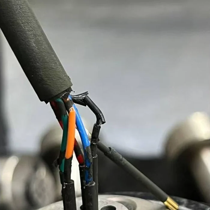
The two teardown photographs below document actual customer failure cases analyzed by CASMO engineering. In both builds, thin-wall FEP insulated primary cores were jacketed with a cross-linked elastomer outer sheath — a glossy black cross-linked PUR jacket in Figure 01, and a matte black cross-linked rubber jacket in Figure 02. Although both outer jackets cured cleanly with excellent exterior toughness, the cross-linking process embrittled the underlying FEP insulation to the point of total mechanical collapse.
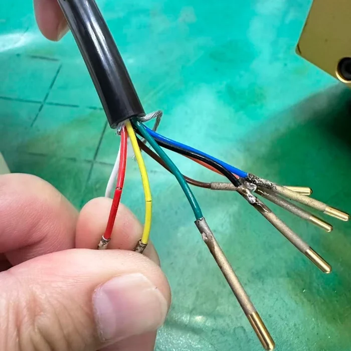
- Classic Embrittlement Signature (Figure 01): Unirradiated FEP exhibits 250%–350% elongation at break and stretches plastically before tearing. Notice how the red and yellow FEP cores under the cross-linked PUR jacket show zero necking — instead snapping with razor-sharp transverse hairline fractures like dry glass.
- Catastrophic Insulation Spalling (Figure 02): At higher cumulative cross-linking stress inside the cross-linked rubber assembly, the black FEP core lost virtually all cohesive tensile strength, shattering off the copper strands right at the connector strain-relief zone where electrical shorting risk is highest.
- Why Final Visual Inspection Misses It: Because the outer jacket hides the cores completely until end stripping, neither defect can be screened visually on bulk cable reels — eliminating the incompatibility at the BOM stage is the only reliable defense.
Polymer Physics Explained: Why E-Beam Destroys PTFE & FEP Yet Cross-Links ETFE & PVDF
Understanding chain scission vs. cross-linking ratio across the fluoropolymer family
A common source of engineering confusion is hearing that aerospace wire standards such as SAE AS 22759/32–/46 use irradiated cross-linked fluoropolymers — and mistakenly assuming all fluoropolymers tolerate electron-beam curing. In radiation polymer chemistry, every plastic exhibits a competing ratio between G(X) (cross-linking yield) and G(S) (main-chain scission yield) when struck by high-energy electrons or gamma rays.
Fully perfluorinated polymers — PTFE (polytetrafluoroethylene), FEP (fluorinated ethylene propylene), and PFA (perfluoroalkoxy alkane) — have carbon backbones surrounded exclusively by fluorine atoms (–CF2– / –CF3). Because the C–F bond is extraordinarily strong (~485 kJ/mol) compared to the C–C backbone bond (~348 kJ/mol), ionizing energy preferentially cleaves the C–C main chain rather than knocking off pendant atoms to create inter-chain bridges. In oxygen-bearing air at ambient factory temperatures, broken chain ends oxidize into peroxy radicals and terminate permanently, slashing molecular weight with every kilogray of absorbed dose.
PTFE is among the most radiation-sensitive engineering polymers known: measurable loss of elongation begins around 1 to 5 kGy, and by 20–50 kGy PTFE turns chalky and fragile. FEP tolerates marginally higher dose than PTFE in inert vacuum or elevated melt-state specialized processes, but under standard commercial air-atmosphere E-beam doses of 100 to 200 kGy used to cure XLPE, XLPO, cross-linked PUR, or cross-linked rubber jackets, FEP still undergoes drastic chain scission, severe embrittlement, and release of trace hydrofluoric acid (HF) gas that corrodes tinned/silver-plated conductors and braid shields.
By contrast, partially fluorinated polymers such as ETFE (ethylene tetrafluoroethylene) and PVDF (polyvinylidene fluoride) contain alternating –CH2– hydrogen units along the backbone. Under electron-beam irradiation (aided by cross-linking co-agents), weaker C–H bonds cleave first to generate stable carbon radicals along intact polymer chains, which couple cleanly into a tough 3D thermoset network (XL-ETFE / XL-PVDF) with enhanced cut-through resistance and higher solder-iron stability.
Thermal & Moisture Failure Mechanisms: Peroxide CCV, Silane Baths, and HAV Silicone Ovens
Even without radiation, heat and curing water can destroy thin-wall FEP core geometry
Avoiding electron-beam irradiation does not automatically make every other cross-linked jacket safe over FEP or PTFE cores. Each chemical or thermal vulcanization route carries its own mechanical, thermal, or moisture boundary condition:
- Chemical Peroxide CCV / VCV Vulcanization (Hard No Over FEP): Dry-cure nitrogen or steam CCV tubes run between 280°C and 400°C at 8–16 bar pressure. Because FEP melts between 255°C and 275°C (and softens rapidly above 220°C–240°C under radial extrusion pressure), FEP cores inside a CCV tube flatten, shift off-center, fuse to neighboring cores, and lose dielectric withstand and impedance symmetry.
- Silane Moisture Cross-Linking (Not Recommended for Multi-Core / Shielded Bundles): Curing a silane-grafted XLPE jacket requires 4 to 24+ hours of immersion in 80°C–95°C hot water or pressurized steam. While FEP and PTFE tolerate 95°C thermally, capillary action draws water through cable ends and pinholes into stranded braids and core interstices — causing copper oxidation, darkened shields, degraded insulation resistance, and unstable mutual capacitance.
- Hot-Air Vulcanized (HAV) Silicone Rubber Over FEP Cores (Default: Not Recommended / Conditional Only): Conventional peroxide-cured silicone jackets pass through hot-air vulcanization ovens running 300°C–350°C. Even short dwell times risk softening thin-wall FEP cores, deforming twisted pairs, or causing conductor migration through the insulation wall. Consequently, CASMO treats FEP core + HAV Silicone jacket as Not Recommended by default; it is only evaluated as a conditional engineering exception when a dedicated thermal barrier tape (such as PTFE, mica, or fiberglass tape) is paired with low-temperature platinum-catalyzed (addition-cure) silicone cured near 180°C–220°C and verified for concentricity.
- Why PTFE Core + HAV Silicone Jacket Works Reliably: Unlike FEP (~260°C melt point), paste-extruded PTFE has a crystalline melting point of 327°C and remains a high-viscosity non-flowing gel even above its melt transition. Pairing PTFE primary cores (wrapped with a thin separator tape) inside a hot-air vulcanized Silicone Rubber outer jacket provides a wide, proven production safety margin.
Core-to-Jacket Process Compatibility Matrix for Hybrid Multi-Core Cables
Quick BOM screening table for harness engineers before releasing drawings for RFQ
Use the matrix below during initial cable architecture reviews to separate proven production combinations from high-risk or physically incompatible cross-linked jacket callouts.
| Outer Jacket Process & Polymer | Over FEP Core (Tm ~260°C) | Over PTFE Core (Tm 327°C) | Over ETFE / XL-ETFE Core | Over XLPE / XLPO Core | Primary Engineering Mechanism / Risk |
|---|---|---|---|---|---|
| E-Beam Cross-Linked Jacket (XLPE, LSZH XLPO, X-PUR, X-Rubber) | Incompatible (Hard No) | Incompatible (Hard No) | Compatible (verify dose) | Compatible | 100–200 kGy radiation causes severe C–C chain scission and brittle fracture in PTFE/FEP (see Figures 01 & 02); ETFE and XLPE tolerate controlled E-beam curing |
| Chemical Peroxide CCV Jacket (XLPE, EPDM, CPE Rubber) | Incompatible (Hard No) | Not Recommended | Not Recommended | Conditional (thick power) | 280°C–400°C high-pressure curing tube melts FEP cores and risks thermal deformation/volatile attack on thin-wall signal cores |
| Silane Water/Steam Cure Jacket (Sioplas / Monosil XLPE) | Not Recommended (multi-core) | Not Recommended (multi-core) | Not Recommended (multi-core) | Conditional (unshielded LV) | 80°C–95°C hot-water/steam bath causes capillary moisture wicking into braided shields, conductor tarnish, and capacitance drift |
| Hot-Air Vulcanized (HAV) Silicone Rubber Jacket | Default: Not Recommended (Conditional Only*) | Compatible (Proven Standard) | Conditional (temp limited) | Incompatible / High Risk | 300°C–350°C peroxide HAV ovens soften FEP; PTFE's 327°C non-melt gel holds geometry cleanly. *FEP requires barrier tape + low-temp Pt-cure review |
| Thermoplastic Jacket — Non-Cross-Linked (TPU/PUR, TPE, FEP, PFA, ETFE, PVC) | Compatible (Proven Standard) | Compatible (Proven Standard) | Compatible (Proven Standard) | Compatible (Proven Standard) | Extruded below core melt limits with zero irradiation, zero steam, and zero vulcanization ovens — full mechanical & dielectric safety margin |
Important specification wording tip: When calling out a Polyurethane (PUR) outer jacket over FEP or PTFE cores on an engineering drawing, explicitly state 'Thermoplastic Polyurethane (TPU/PUR — non-irradiated)' so no supplier substitutes an E-beam cross-linked PUR grade.
Three Proven Production-Safe Alternatives to Replace Incompatible Hybrid BOMs
How to preserve your exact mechanical, thermal, or impedance goals without core embrittlement
Whenever an OEM drawing crosses our engineering desk calling for FEP cores inside a cross-linked XLPE, irradiated PUR, cross-linked rubber, or standard HAV silicone jacket, we rarely need to compromise the customer's end-use performance. Almost every application maps cleanly onto one of three zero-risk, volume-proven architectures:
- Architecture 1 — Keep FEP Cores + Switch to Non-Cross-Linked Thermoplastic Jacket (Best for Drag-Chain, Sensors & Impedance): Keep thin-wall FEP primary cores for long continuous splice-free lengths and tight 100Ω/120Ω impedance, and specify an ether-based thermoplastic PUR (TPU) jacket for extreme oil/coolant/drag-chain abrasion, a thermoplastic TPE jacket for flexible 100% PFAS-free outer feel, or an all-fluoropolymer FEP/ETFE outer jacket for 150°C–200°C chemical immersion. Zero radiation, zero ovens, zero embrittlement.
- Architecture 2 — Upgrade Primary Cores from FEP to PTFE + Hot-Air Vulcanized Silicone Jacket (Best for 180°C–200°C Ultra-Flexible Robotics & Medical): When you genuinely need a supple, limp, high-temperature Silicone Rubber outer jacket, upgrade the internal primary cores from FEP to paste-extruded PTFE (327°C melt point, non-flowing above Tm) with a low-friction PTFE/non-woven separator wrap. PTFE withstands silicone curing effortlessly while keeping bundle O.D. compact.
- Architecture 3 — Switch Primary Cores to ETFE / XL-ETFE or XLPE + E-Beam Cross-Linked Jacket (Best for Aerospace, Rail & High-Abrasion Irradiated Assemblies): When the end standard strictly mandates an electron-beam cross-linked outer jacket (such as EN 50264 rolling stock, nuclear/radiation zones, or irradiated abrasion-resistant harnesses), replace PTFE/FEP cores with radiation-compatible XL-ETFE (150°C–200°C) or 100% PFAS-free E-beam XLPO/PEEK so both core and jacket survive irradiation with zero chain scission.
Frequently Asked Questions
- Can you put an electron-beam cross-linked XLPE, PUR, or rubber jacket over FEP or PTFE insulated wires?
- No. Electron-beam irradiation at the 100–200 kGy dose required to cross-link an outer jacket causes severe C–C backbone chain scission in PTFE and FEP cores underneath. Even if the finished cable passes factory spark tests on the reel, the embrittled FEP/PTFE cores develop transverse cracks and fracture when stripped or flexed into connectors.
- Why did my FEP cores crack inside a PUR jacket when PUR is normally safe over FEP?
- Standard thermoplastic Polyurethane (TPU/PUR) is completely safe over FEP cores because it is extruded at ~190°C–210°C with zero irradiation. Cracking happens when an irradiated (cross-linked) PUR compound is mistakenly substituted for higher heat or weld-spatter resistance, exposing the underlying FEP cores to electron-beam degradation. Always specify non-irradiated thermoplastic PUR explicitly on drawings over FEP/PTFE cores.
- Can a Silicone Rubber outer jacket be vulcanized over FEP insulated primary cores?
- CASMO does not recommend FEP cores under hot-air vulcanized (HAV) Silicone Rubber jackets by default, because conventional peroxide HAV ovens run at 300°C–350°C — well above FEP's ~260°C melt point — risking core softening, flattening, and eccentricity. For silicone-jacketed hybrid cables, upgrade primary cores to PTFE (327°C non-melt). FEP + Silicone is only considered conditionally after formal engineering review using thermal barrier tape and low-temperature platinum-catalyzed addition curing.
- Why can SAE AS 22759 XL-ETFE wire be electron-beam irradiated when PTFE and FEP cannot?
- PTFE and FEP are perfluorinated (only C–C and C–F bonds), so ionizing radiation breaks the weaker C–C polymer backbone (chain scission). ETFE and PVDF contain alternating –CH2– hydrogen groups along the chain; under controlled E-beam irradiation with co-agents, C–H bonds cleave preferentially to form stable inter-chain cross-links rather than severing the backbone.
- Does silane moisture cross-linking avoid the radiation problem over FEP or PTFE cores?
- Silane cross-linking avoids electron-beam chain scission, but it introduces a different multi-core failure mode: 80°C–95°C hot-water or steam curing baths drive capillary moisture into shielded multi-conductor assemblies, oxidizing tinned/bare copper braids and destabilizing mutual capacitance and insulation resistance. Thermoplastic jacketing remains far cleaner and more reliable over FEP/PTFE cores.
- What is the safest outer jacket over FEP cores if I need high abrasion, oil resistance, and continuous flexing?
- Specify a non-irradiated ether-grade thermoplastic Polyurethane (TPU/PUR) outer jacket wrapped over a low-friction separator tape (and braided shield if EMI protection is needed). You retain full FEP electrical/thermal integrity on the cores plus industrial drag-chain abrasion, coolant, and hydrolysis endurance on the outside.
Regulatory & Engineering References
- ASTM / Polymer Radiation Literature — Radiation Stability & Chain-Scission Behavior of Perfluorinated Polymers (PTFE, FEP, PFA) vs. Cross-Linkable Fluoropolymers (ETFE, PVDF).
- SAE International — SAE AS 22759 Insulated Electrical Wire Specifications (PTFE, FEP, and Irradiation Cross-Linked XL-ETFE Series).
- UL Standards — UL 758 Standard for Appliance Wiring Material (AWM) (FEP Styles 1330/1332, PTFE Styles 1180/1213, Silicone & PUR Jacketed Multi-Conductor Styles).
- NEMA — NEMA HP3 (PTFE) & NEMA HP4 (FEP) High-Temperature Hook-Up Wire Specifications.
- CASMO CABLE LLC — Internal Failure Analysis Archive: Irradiated Cross-Linked PUR & Cross-Linked Rubber Jacket Teardowns Over FEP Primary Cores.